How to Program the MGC and MGC Pro Controller for Magnetic Barrier Gates
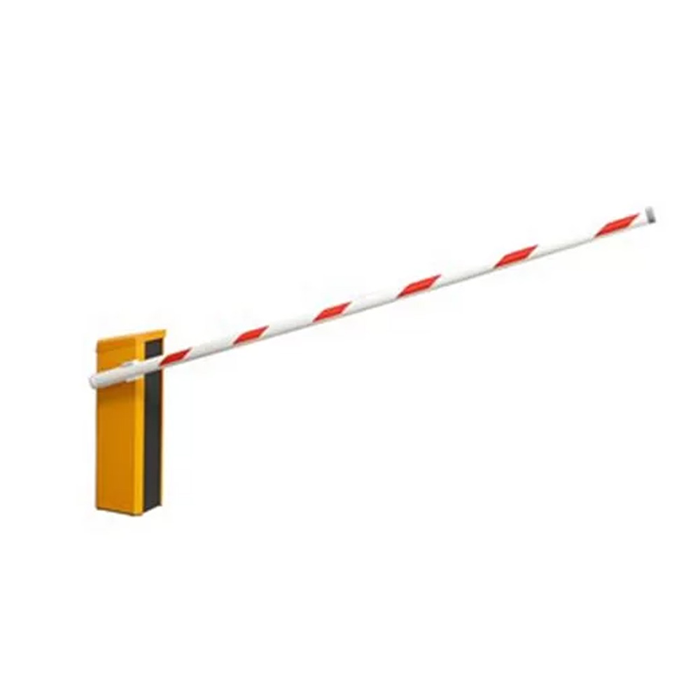
Magnetic Autocontrol barrier gate openers are widely recognized for their durability, high-speed operation, and seamless integration with access control systems. Whether securing a parking facility, toll booth, or industrial entrance, these automated barriers are engineered to manage vehicle flow efficiently and reliably. However, proper programming of the unit is essential to ensure peak performance and compatibility with your site's specific requirements. From setting operational parameters to customizing safety features, understanding the programming process can significantly enhance functionality and extend the system's service life.
This guide will walk you through the key steps to program your Magnetic Autocontrol barrier gate opener, including initial setup, control board identification, basic configuration, and advanced features. Whether you're an installer setting up a new unit or a technician adjusting settings for an existing system, this article provides a practical, model-aware approach. Before diving in, ensure you're working with the correct control board version and have reviewed all relevant safety procedures; accuracy and precaution go hand-in-hand when programming these sophisticated systems.
Safety First: Preparation Before Programming
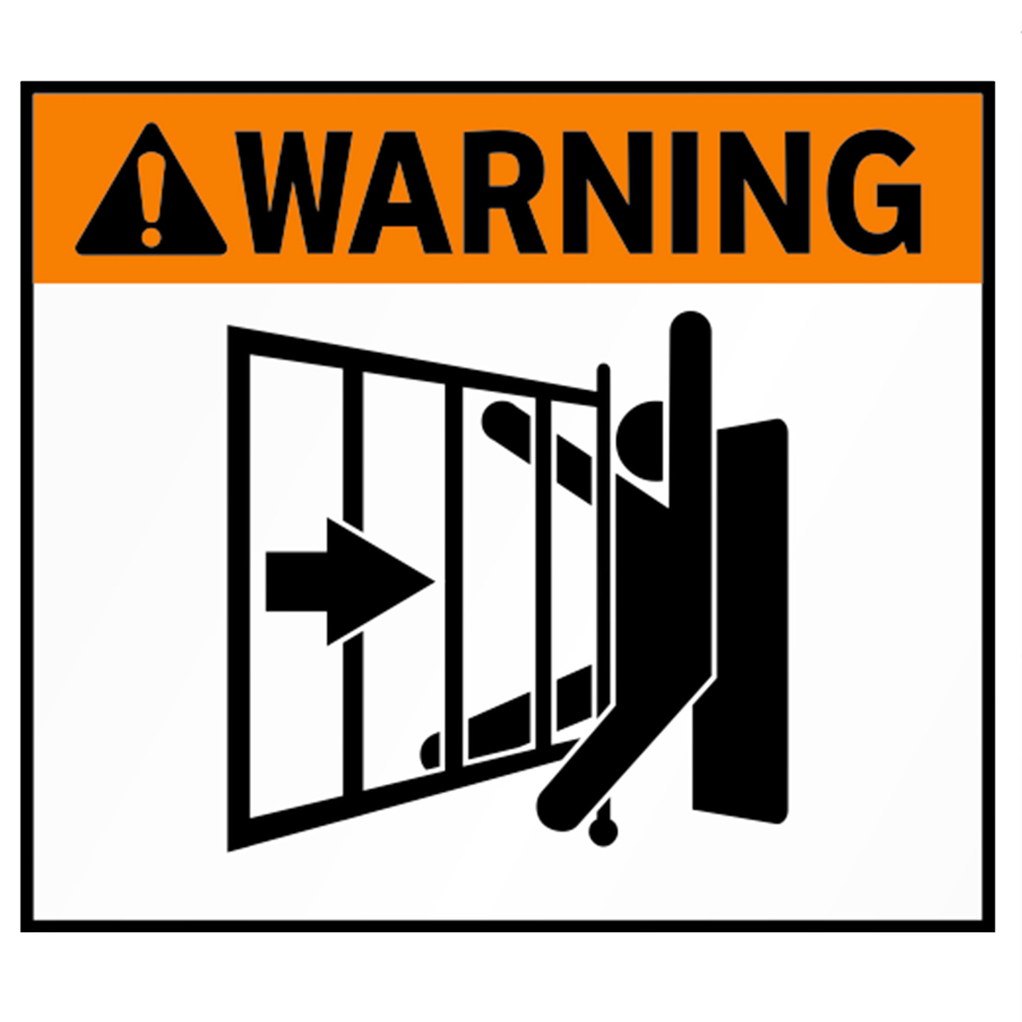
Before you begin programming a Magnetic Autocontrol barrier gate, you must follow safety protocols to protect yourself and the equipment.
Power Safety
- Always disconnect power before opening the unit or accessing internal components.
- Even inactive systems may carry residual voltage or receive input signals that could trigger movement.
- Use anti-static protection when handling the control board, especially on MGC Pro or Advanced models.
Tools & Equipment Checklist
- Flathead screwdriver
- Multimeter or voltmeter
- Laptop with Magnetic software (if applicable)
Documentation to Review
- Model-specific installation and programming manual
- Control board wiring diagrams
- Factory default settings list
Identifying the control board before starting helps avoid mistakes and ensures the programming process goes smoothly. Skipping these prep steps could lead to errors or system malfunctions.
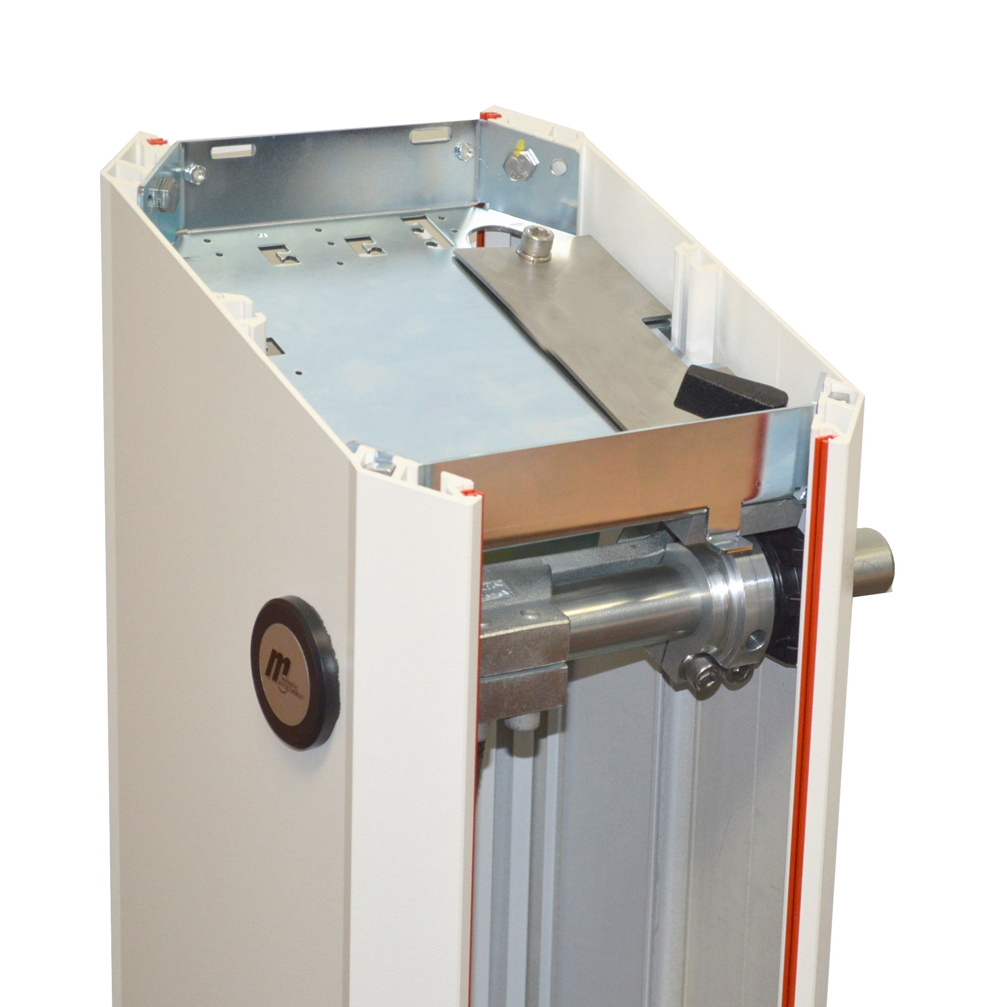
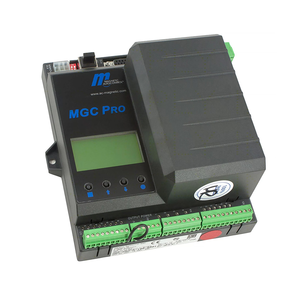
Identifying the Control Board
You can locate the control board inside the main housing of the barrier. A label or part number is usually printed directly on the board. If you're unsure, refer to the model-control board chart below. Having the correct board reference on hand will save time and help you avoid applying the wrong settings or instructions.
Digital Inputs, Outputs, and Output Relays
The MGC and MGC Pro controllers allow you to connect external signals, buttons, sensors, and feedback devices using digital inputs and outputs. While the MGC has pre-set functions, the MGC Pro offers flexible programming for each terminal. Below are clear steps and guidance on how to configure them.
How to Identify and Use Digital Inputs (IN1-IN8)
- Locate terminals labeled IN1 to IN8 on the controller board.
- Connect 24V DC signal wires from push buttons, access control systems, loop detectors, or other devices.
- On an MGC Pro unit, go to the controller menu and assign any of the following functions to any input:
- Open (pulse or maintained)
- Close
- Stop
- Emergency Open
- Auto Close Start
- Pedestrian Mode / Partial Opening
- Loop Detector Override
How to Program Input Functions (MGC Pro Only)
- Use the arrow keys to navigate to the "In-/Outputs" menu.
- Select the input (IN1-IN8) you want to modify.
- Scroll through the list of assignable functions and press Enter to select.
- Save your selection and exit the menu. The input will now trigger the new function.
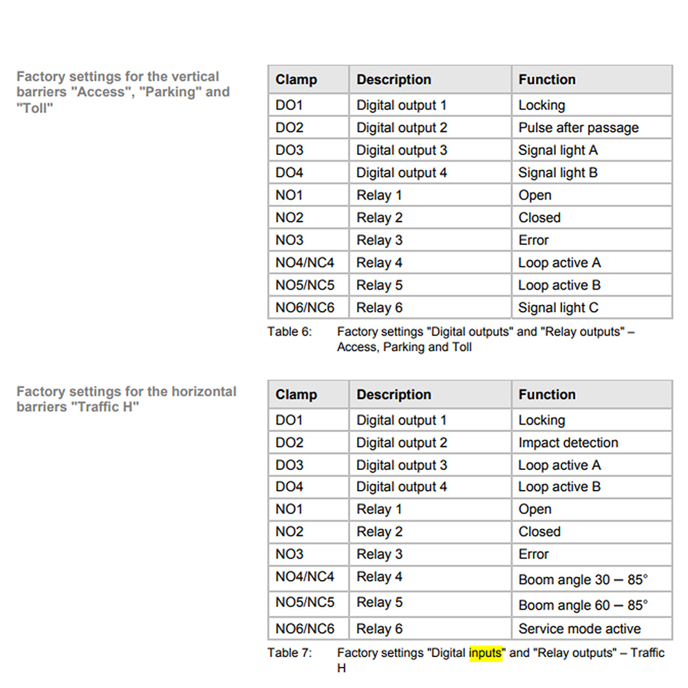
How to Use Digital Outputs and Relays
- Locate output terminals OUT1 to OUT6 or labeled relay connections (K1, K2, etc.).
- Connect these to external devices such as traffic lights, buzzers, or monitoring systems.
- By default, outputs are assigned as:
- Relay 1: Status output (e.g., gate open/closed)
- Relay 2: Fault or error output
- On MGC Pro, you can reassign outputs by:
- Navigating to "In-/Outputs" in the menu.
- Selecting an output (OUT1-OUT6).
- Choosing from logic-based conditions such as:
- Barrier Open
- Barrier Closed
- Drive Active
- Error Present
- Loop Occupied
How to Wire Inputs and Outputs Safely
- Use shielded cables to reduce electrical interference.
- Keep input/output wiring away from high-voltage or motor cables.
- Ensure the system is powered off before making any connections.
- Follow proper grounding and surge protection procedures.
- Only trained technicians should perform wiring or reconfiguration.
For complete programming instructions, wiring diagrams, and advanced configuration options, please refer to the official controller manual below.
View Full MGC/MGC Pro ManualBasic Settings and Programming Configuration
This section covers adjusting essential controller settings like language and passwords, selecting programming modes, configuring barrier motion, and defining behavior during power failures.
How to Change the Display Language
- Navigate to the main menu using the arrow keys on the controller display.
- Select the "Basic Settings" menu option.
- Scroll to "Language" and press Enter.
- Choose your preferred language from the available list.
- Press Enter again to confirm.
How to Set or Change the Controller Password
- In the "Basic Settings" menu, locate the "Password" option.
- Enter the current password if prompted (factory default may be blank or a preset code).
- Choose a new 4-digit numeric password and confirm it.
- This password will now be required to access settings menus.
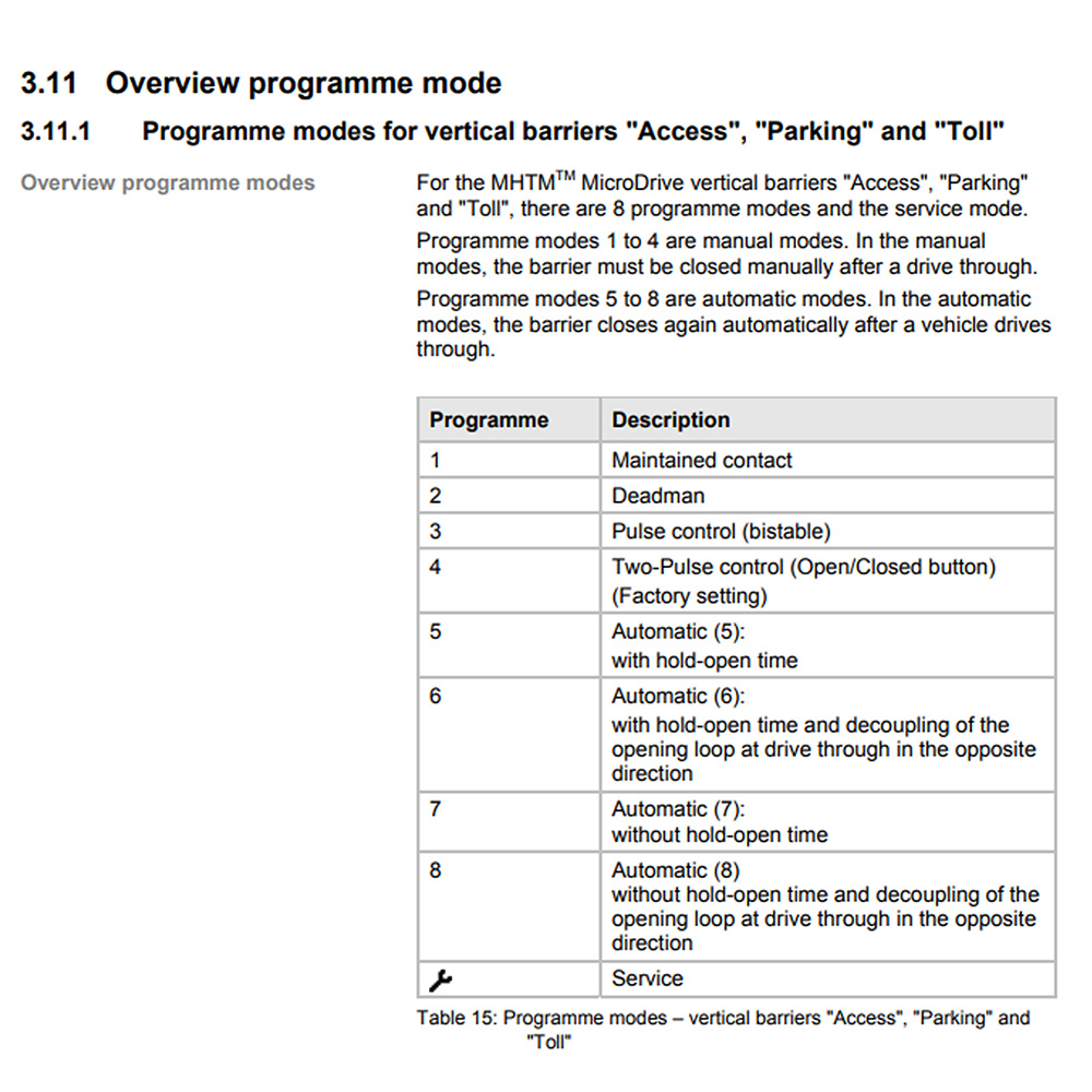
How to Choose a Programming Mode
The controller offers several modes for different types of operation. These determine how the barrier reacts to input signals.
- Go to the "Function" menu.
- Select "Program Mode" and choose from one of the following:
- Mode 1: Hold-to-run (manual opening/closing)
- Mode 2: Deadman control (open/close only while signal is active)
- Mode 3: Pulse/bistable control (toggle open/close)
- Mode 4: Two-pulse control (one input opens, one closes)
- Modes 5-8: Automatic modes with customizable logic for entry/exit scenarios
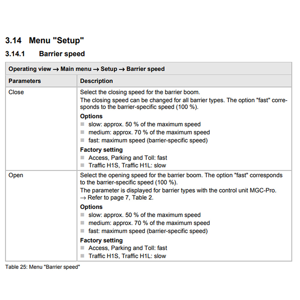
How to Adjust Barrier Speed and Closure Settings
- From the "Setup" menu, select "Speed and Timing".
- Adjust these parameters as needed:
- Open Speed: Sets how fast the arm raises
- Close Speed: Sets how fast the arm lowers
- Start Delay: Wait time before barrier begins to move
- Braking Ramp: Gradual slowdown to prevent sudden stop
- Automatic Close Time: Sets how long to wait before the barrier automatically closes
How to Set Behavior for Power Failure
- Go to the "Setup" > "Power Failure" menu.
- Select the desired action during a power outage:
- Remain Closed
- Remain Open
- Open Immediately
- Confirm and save the selection.
For complete programming instructions, wiring diagrams, and advanced configuration options, please refer to the official controller manual below.
View Full MGC/MGC Pro ManualSpecial Functions and Attachments
This section explains advanced options such as closure logic, Single-Dual configurations, signal light integration, locking options, and external accessory modules.
How to Configure Closure Functions
- Navigate to the "Special Functions" menu.
- Enable or adjust the following settings as needed:
- Tailgating Prevention: Closes the barrier immediately after vehicle passes
- Loop Detector Override: Allows opening even if loops detect a vehicle
- Pedestrian Mode: Opens the barrier to a shorter position
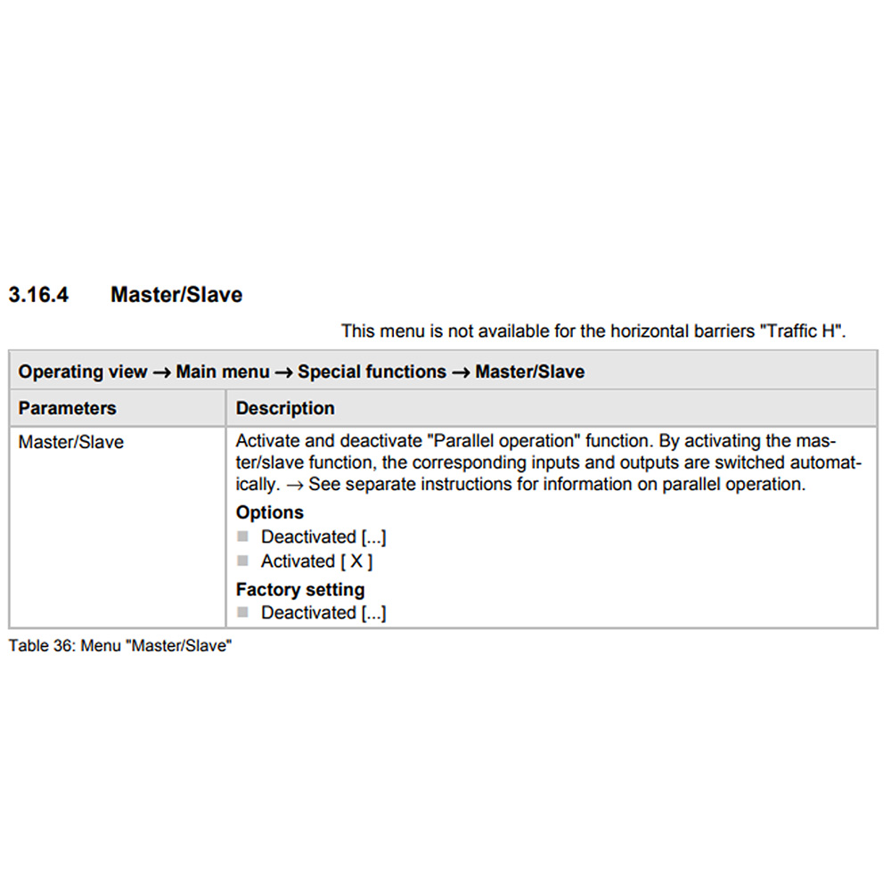
How to Set Up Single-Dual Operation
- Connect both controllers via RS485 interface (requires compatible wiring and barrier models).
- On the primary controller, set role to "Master" in the "Attachments" menu.
- On the secondary controller, set role to "Slave".
- Ensure both units are programmed with synchronized timing and motion profiles.
How to Integrate Signal Lights
- Wire red and green lights to available relay outputs (Relay 1 and Relay 2 are commonly used).
- In the "Outputs" > "Assign Functions" menu, configure outputs as:
- Relay X: Green light ON when barrier is open
- Relay Y: Red light ON when barrier is closed or moving
- Use logic outputs for feedback to traffic management systems if needed.
How to Enable Locking Systems
- Connect electric or magnetic locks to designated output terminals.
- In the "Attachments" menu, enable lock control.
- Configure the timing so the lock disengages just before the arm raises and re-engages after it lowers.
How to Add and Configure Optional Attachments
- Attach compatible modules such as:
- Radio receiver boards
- Battery backup systems
- Loop detector cards
- RS-485/RS-232 communication modules
- Go to the "Attachments" menu to activate and configure connected modules.
- Set input/output behavior or communication settings for each attachment as required.
For complete programming instructions, wiring diagrams, and advanced configuration options, please refer to the official controller manual below.
View Full MGC/MGC Pro ManualFinal Testing
Before putting the barrier gate into full operation, a final test ensures that all inputs, outputs, and safety functions are working correctly. This process should be documented and, if required, approved by site supervisors or clients.
Run Test Cycles
- Trigger the gate using each input method (loop, button, access reader) to verify activation.
- Ensure the gate fully opens and closes without hesitation, abnormal sounds, or misalignment.
Verify Safety Devices
- Break the beam of any photocells or step onto safety loops to ensure the gate halts or reverses.
- Use a soft object to test obstruction detection if configured for reverse-on-contact.
Check Output Devices
- Ensure signal lights, status relays, or alarms respond correctly during barrier operation.
- Record the state of outputs for both open and closed cycles.
Log and Save Settings
- On MGC Pro and H100 boards, export the configuration file using MHTM™ Config Tool.
- Label the gate with the firmware version, configuration date, and service contact info.
Troubleshooting Tips
If your Magnetic Autocontrol barrier gate is not functioning as expected, quickly diagnose and resolve common issues using the following troubleshooting steps. Always ensure power is disconnected before making any wiring adjustments.
Check LED Status Indicators
- Control boards have diagnostic LEDs to indicate faults or input/output activity.
- Refer to the board's legend (typically printed on the PCB) or manual for LED behavior.
- Blinking red or amber indicates an input conflict, safety device activation, or obstruction.
Common Error Messages
- E01-Loop Fault: Check loop wiring, sensitivity settings, and ground connection.
- E02-Arm Obstruction: Barrier arm hit or blocked; reset fault and check for physical damage.
- No Response from Input: Verify input device voltage and signal wiring to the correct terminal.
Resetting the System
- Use the Reset button on the board or cycle power to clear temporary faults.
- On MGC Pro and H100 boards, view and clear error logs using the software.
- Persistent issues may require firmware refresh or board replacement if damaged.
Magnetic Barrier Gate Opener Programming Review
Programming a Magnetic Autocontrol barrier gate opener may initially seem complex, but it becomes a manageable, repeatable process with the right preparation and broad knowledge. Each step plays a key role in ensuring reliable, long-term gate performance, from identifying your control board to fine-tuning advanced logic and verifying safety devices.
Whether configuring a high-speed Toll model or setting up a basic Access unit, following proper setup and programming procedures will save you from operational headaches later. Always reference the correct firmware version, and use available software tools for more advanced control and diagnostics.
If you have any questions or need support, please reach out. We are always happy to help.